
Inspection standards for accuracy of horizontal band saws
Inspection scope of horizontal band saw
This part of JB/T 4318 specifies the requirements and inspection methods for the geometric accuracy and working accuracy of horizontal band saws.
This section applies to the band saw machine (hereinafter referred to as machine tools) with a maximum sawing diameter of 250 mm to 2 000 mm. For other specifications of horizontal band saws, please refer to this section.
General requirements
✦ Adjust the horizontal band saw installation level according to 3.1 in GB/T 17421.1—1998. Place a level in the center of the workbench. The readings of the level in both the longitudinal and transverse directions do not exceed the specifications in the instruction manual.
✦ All linear dimensions in this section are expressed in millimeters (mm).
✦ When the actual measured length is different from the length specified in this section, the tolerance shall be converted according to the measurable length according to the provisions of 2.3.1.1 in GB/T 17421.1-1998. When the conversion result is less than 0.01 mm, it is still calculated as 0.01 mm.
✦ During various geometric accuracy inspections, manual or machine tool low-speed movement should be used.
✦ The working accuracy inspection of machine tools should be carried out on the specified test pieces. The material of the specimen is 45 steel, in normalized state, the hardness is 170 HBW ~ 200 HBW, and the hardness is uniform. The surface roughness value Ra of the specimen should not be greater than 6.3 mm.
✦ The working accuracy of large-sized forged castings and workpieces without surface treatment can be measured directly by placing a square ruler on the horizontal datum plane of the machine tool workbench or using other indirect measurement methods.
✦ The metal band saw blade is allowed to be replaced during the inspection of machine tool geometric accuracy and working accuracy. The metal band saw blade used should comply with the regulations of GB/T 21954.2-2008.
✦ The order of accuracy inspection items listed in this section does not represent the actual order of inspection. For the convenience of assembly and disassembly of inspection tools and inspection, inspection can be carried out in any order.
✦ According to the agreement between the user and the manufacturer, the inspection items and inspection methods can be adjusted appropriately.
Geometric accuracy inspection
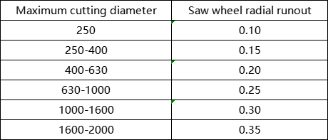
Saw wheel radial runout
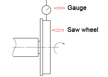
Inspection tools: dial indicator
Measurement methods:
Inspection method (according to the provisions of 5.6.1.2.2 in GB/T 17421.1-1998)
Fix the magnetic base of the dial indicator on the fixed part of the band saw, make its probe vertically touch the outer cylindrical surface of the saw wheel, and rotate the saw wheel for inspection. The largest difference in dial indicator readings is radial runout.
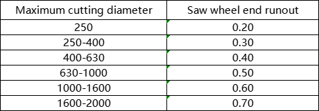
Saw wheel end runout

Inspection tools: dial indicator
Testing method:
(According to the provisions of 5.6.3 in GB/T 17421.1-1998)
Fix the magnetic meter base on the fixed part of the band saw, make the measuring head vertically touch the edge of the end face of the saw wheel, and rotate the saw wheel for inspection. The maximum difference in dial indicator readings is the end face runout tolerance.
The parallelism of the downward movement of the saw frame to the ideal saw section of the specimen

Tolerance requirements:
0.1mm deviation allowed on 100mm measuring length.
validation tools:
- Dial indicator, square box
- Vernier caliper, square ruler
Testing method:
(According to the provisions of 5.4.4.2 in GB/T 17421.1-1998)
Method 1: Tension the metal band saw blade, place the square box that replaces the saw section of the specimen on the workbench, and place one side of the square box against the fixed clamping surface of the work vise. Place the dial indicator base in the middle of the saw frame so that its probe touches the detection surface of the inspection tool vertically. Move the sawhorse for inspection. The maximum difference in the indicator reading is the tolerance of the parallelism of the downward movement of the saw frame to the ideal saw section of the specimen.
Method 2: Place the square on the work surface of the horizontal band saw, with one side of the square close to the fixed clamping surface of the work vise. Keep an appropriate distance between the square and the metal band saw blade, move the saw frame so that the saw blade is positioned from end a to end b, and measure the values at both ends. The difference between the values is the parallelism tolerance.
You can choose one of two methods.
Changes in transverse position of saw beam
It is only suitable for horizontal band saws with hinged structure whose maximum sawing diameter is less than or equal to 400.

Tolerance: 0.25mm when force F=100 N
Inspection tools: dial indicator, spring scale
Testing method:
Fix the magnetic gauge base in the middle of the saw beam so that the measuring head of the dial indicator touches the side of the bench vise fixing clamp vertically. Use a spring scale to alternately apply force F back and forth to the saw belt tensioning handwheel for inspection. The maximum value of the dial indicator reading is the tolerance of the saw frame’s lateral position change.
Perpendicularity of the fixed clamping face of the work vise to the side of the metal band saw blade

Tolerance: 0.10mm on 100mm measuring length
Inspection tools: square ruler, feeler gauge
Testing method:
(According to the provisions of 5.5.1.2 in GB/T 17421.1-1998)
Place the square square on the work surface, with the short side close to the fixed clamping surface of the work vise, and the other long side lightly against the side of the band saw blade, and check with a feeler gauge. The maximum clearance measured by a feeler gauge is the vertical tolerance of the work vise’s fixed clamping face to the side of the band saw blade.
Repeatable positioning accuracy of the forward and backward motion of the feeding mechanism
Only suitable for horizontal band saws with automatic duty cycle function.

Tolerance: a) 0.10 forward; b) 0.20 backward
Inspection tools: dial indicator
Testing method:
(According to the provisions of 5.4.4.2 in GB/T 17421.1-1998)
Fix the magnetic gauge holder on the workbench and feeding frame of the horizontal band saw so that the dial indicator probe touches both sides of the fixed clamp of the feeding vise vertically. The feeding mechanism will automatically move forward and return 7 times for inspection.
The maximum value of the 7 readings of the indicator is the repeated positioning tolerance of the feeding mechanism.
Metal band saw blade vertical guide accuracy
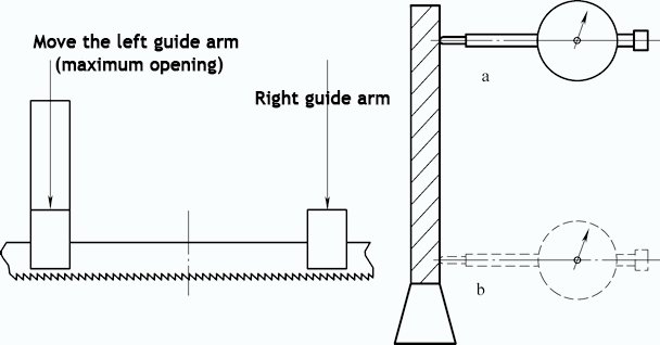
Inspection tools: Dial indicator Inspection method:
(According to the provisions of 5.5.1.2 in GB/T 17421.1-1998)
Move the guide arm and adjust it to the maximum position. The metal band saw blade will naturally be close to the positioning surface of the guide device. Fix the indicator on the horizontal band saw workbench so that its probe vertically touches one side of the band saw blade at the center line of the maximum opening. Turn on Feed the horizontal band saw, move the metal band saw blade position from point a to point b, and check the maximum indicator reading. The maximum value is the tolerance.
Metal band saw blade horizontal guide accuracy
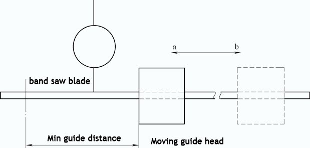
Tolerance: ±0.20 Inspection Tool: Dial Indicator Inspection Method:
(According to the provisions of 5.2.1.2 in GB/T 17421.1-1998)
Fix the magnetic meter holder on the horizontal band saw workbench so that the dial indicator probe touches one side of the band saw blade vertically (as close as possible to the minimum guide position), and slide the guide arm from point a (minimum guide distance) to point b (Maximum guide distance), view the maximum indicator reading. The maximum value is the tolerance.
Angle rotation accuracy

Tolerance: ±30′
Inspection tools: Vernier universal angle ruler
Testing method:
(According to the provisions of 6.4.3 in GB/T 17421.1-1998)
Use a vernier universal angle ruler to measure the angle between the fixed jaw surface and the side plane of the band saw blade. The difference between the measured value and the set value is the tolerance.